立创业思想 做创新研究Drive Machine Drive World


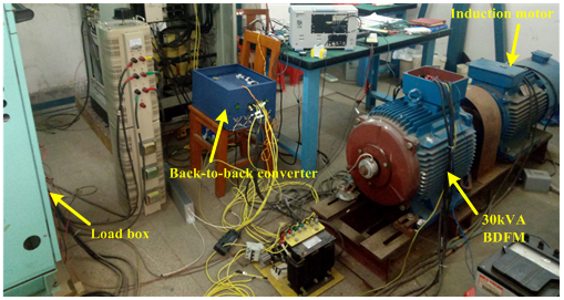
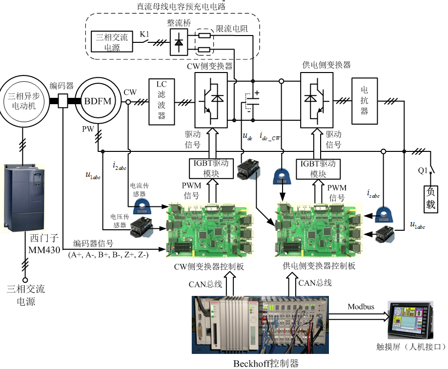
Our research team uses a prototype BDFM with a capacity of 30kVA as a generator. A three phase asynchronous motor of 37kW is connected with BDFM, and the drive of the motor is realized by a SIEMENS MM430 inverter. The core of the experimental system is two PWM converters: the CW side converter and the power supply side converter. The two PWM converters all use IGBT as switch device, and their control is achieved by two relatively independent control panels (CW side converter control panel and power supply side converter control panel). The two control boards are designed on the basis of ARM (Freescale MK60FN1M0VLQ12) and FPGA (Altera Cyclone IV), and their hardware configurations are exactly the same, but the control algorithms are different. The PWM pulse signals from the two control panels are isolated and amplified by the IGBT drive module and drive each IGBT. The LEM LT 208-S7/SP1 current sensor is used to measure the three-phase current and PW three-phase current of CW, and the PW three-phase voltage is measured by LEM LV 100 voltage sensor. The measurement result is converted to analog signal of -10V ~ 10V and sent to the control panel of the CW side converter. The position signal of the motor rotor is collected by an incremental encoder and sent to the CW side converter control panel. The encoder type is RHI90, which is made by P+F company. Its accuracy is 1024 lines. In addition, using LT 208-S7/SP1 LEM current sensor, voltage sensor LEM LV 100 measurement power supply side converter AC side current, three-phase PW voltage and DC bus voltage, the measurement results are also converted analog signals for -10V ~ 10V, sent to the power supply side converter control board. The CW side converter and the power supply side converter are connected through the DC bus. There are 4 thin-film capacitors connected on the DC bus. The capacitance and the rated voltage of each capacitor are 4000uF and 700V, so the total capacitance of the DC bus capacitor is 16000 F. The experimental platform of the precharge circuit used in power system before start of the DC bus capacitor for charging, which makes the system startup CW side converter can work to achieve the excitation control of CW, when the start after the completion of the switch will be removed from the control loop. In addition, a Beckhoff controller is also configured to control two PWM converters in the experimental system. The Beckhoff controller communicates with the CW side converter control panel and the power supply side converter control panel through the CAN bus. It also connects with a touchscreen through the Modbus bus to achieve human-machine interaction. The Beckhoff control program contains the timing logic of the whole system, as well as fault detection and various protection functions.
地址:湖北省武汉市洪山区珞喻路1037号 邮箱:weixu@hust.edu.cn 传真:18672395238 联系人: 徐伟
版权所有:华中科技大学CECS能量转换系统研究组